|
TYPICAL SPECIFICATIONS
|
| |
|
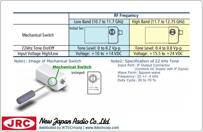
| RF Frequency |
(Universal Ku-band) |
| Low Band: |
10.7 to 11.7 GHz |
| High Band: |
11.7 to 12.75 GHz |
| |
|
| IF Frequency |
|
Low Band:
|
950 to 1,950 MHz |
High Band:
|
1,100 to 2,150 MHz |
| |
|
| Local Frequency |
|
Low Band:
|
9.75 GHz
|
High Band:
|
10.6 GHz |
| |
|
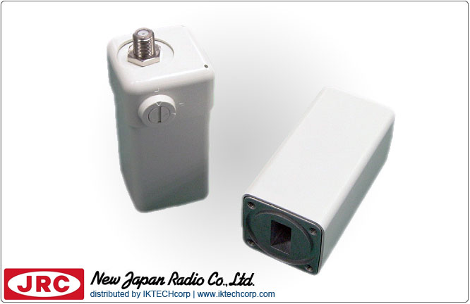
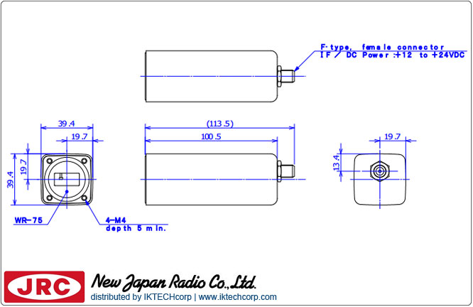
| Input Interface |
Waveguide, WR75 (with Groove) |
| Output Interface |
N-type, female (50 ohm)
|
| Noise Figure (at +25 C) |
0.8 dB typ. |
| Conversion Gain (at +25 C) |
48 dB min., 62 dB max. |
| Input Voltage |
+24 VDC (+12 to +24 VDC) |
| |
|
| L.O. Phase Noise (SSB) |
|
| @ 100 Hz |
-50 dBc/Hz max. |
| @ 1 kHz |
-70 dBc/Hz max. |
| @ 10 kHz |
-75 dBc/Hz max. |
| @ 100 kHz |
-85 dBc/Hz max. |
| |
|
| L.O. Leakage Level |
|
| at the IF Output Connector |
-40 dBm max. |
| at the RF Input Flange |
-60 dBm max. |
| |
|
| Spurious |
|
| Fixed frequency spur, unrelated to test CW signal (Measured at specified IF band). |
-120 dBm max.at input
|
| With test CW signal -10 dBm IF output (Measured at specified IF band). |
-40 dBc max. |
| |
|
| Input V.S.W.R. |
2.5 : 1 typ. |
| Output V.S.W.R. |
2.3 : 1 max. |
| Power Requirement |
+24 VDC (+12 to +24 VDC) |
| Current Drain |
200 mA max. |
| |
|
| Mechanical & Environmental ▼ |
|
| Temperature Range (ambient) |
-40 to +60 C (operating)
-40 to +80 C (storage) |
Dimension & Housing
(without Interface Connectors/Switches) |
82.2 mm (L) x 40 mm (W) x 40 mm (H)
[3.24" (L) x 1.57" (W) x 1.57" (H)] |
| Weight |
240 g [0.53 lbs] |
 Малошумный блок Внешний эталонный разъем N-типа")