| MECHANICAL SPECIFICATIONS |
| |
|
| Az/El Drive |
Motorized AvL Zero Backlash Cable Drive (Patent Pending) |
| Polarization Drive System |
Motorized Rotation of Feed
|
| Reflector Construction |
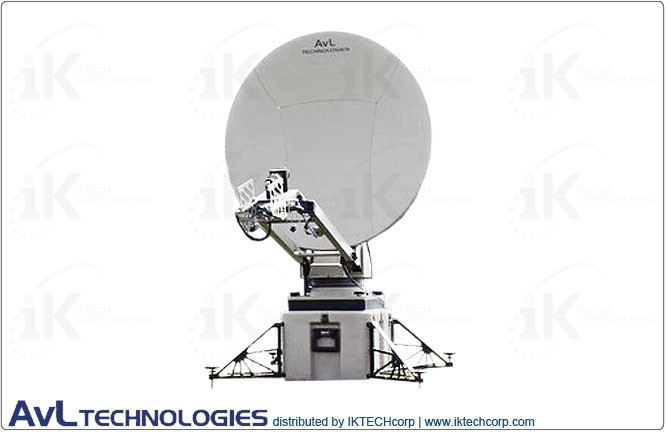
1.2m Segmented 4-piece Carbon Fiber |
| |
|
| Axis Travel ▼ |
|
| Azimuth |
±200° |
| Elevation (reflector boresight) |
5° - 100° of reflector boresight from calibrated inclinometer (El range may vary depending upon CFE) |
| Polarization |
±95° |
| |
|
| Az/El Speed: ▼ |
|
| Slewing/Deploying (typical) |
2°/sec Elevation: 1°/sec |
| Peaking (typical) |
0.2°/sec |
| |
|
| Motors |
24 VDC Variable Speed, Constant Torque |
| |
|
| Standard Interfaces: ▼ |
|
| BUC Mounting |
Feed boom or behind reflector (additional CFE case or optional case required) |
| RF |
Std. 50 ohm Coax (2) at base, cover flange at feed Tx port |
| Electrical |
30 ft. cable with connectors for controller |
| |
|
| Manual/Emergency Drive |
Handcranks for Az and El, Knob on Pol axis |
| |
|
| Transit Configuration (Ku-band): ▼ |
|
| Two rugged, weather-resistant plastic cases, total weight 260 lbs. (typical) |
| Positioner |
27” x 20” x 22”, 110 lbs. max, 100 lbs. typical |
| Outriggers/Feed Boom/Reflector |
43” x 28” x 21”, 150 lbs. max (Includes Ku or Ka Feed), 140 lbs. typical |
| Additional Feeds |
43” x 28” x 21”, 70 lbs typical, dependent on feed options selected |
| |
|
| Set-up Time |
Less than 15 minutes. |
|
| |
| ENVIRONMENTAL SPECIFICATIONS |
| |
|
| Wind – Survival |
80 mph in zenith position
|
| Wind - Operational: ▼ |
|
| Without Anchoring |
30 mph |
| With Anchoring |
30 mph gusting to 40 mph |
| |
|
| Pointing Loss in Wind: ▼ |
|
| Ku-band |
0.1 dB typical, 0.5 dB max |
| Ka-band |
0.3 dB typical, 1.0 dB max |
| X-band |
0.1 dB typical, 0.2 dB max |
| |
|
| Temperature: ▼ |
|
| Operational |
-22° to 125° F (-30° to 52° C) |
| Survival |
-40° to 140° F (-40° to 60° C) |
|
| |
| RF / ELECTRICAL SPECIFICATIONS |
Receive |
Transmit |
| |
|
|
| Feed Type ► |
Std. 2-Port Ku (1.2m Reflector) |
|
|
|
| Frequency Range (GHz) |
10.95 - 12.75 |
13.75 - 14.50 |
| Polarization Configuration |
Linear orthogonal standard |
| Gain (mid-band) @ Horn Interface (dBi) |
41.6 dBi |
43.1 dBi |
| -3dB Beamwidth (mid-band) |
1.5° |
1.2° |
| Antenna Noise Temperature (midband) |
54° K |
|
| Radiation Pattern Compliance |
FCC 25.209, ITU-R S.580-6, IESS 208 |
| Maximum Feed Transmit (Tx) Power |
|
500 watts per port |
| Maximum Allowable Power |
|
-14dBw/4kHz (per FCC) -0dBw/4kHz (per ITU) |
| VSWR |
1.30:1 |
1.30:1 |
| G/T with 50˚ LNB, midband, clear horizon |
21.3 dB/° K (with 50°K LNB) |
|
| |
|
|
| Cross-Polarization Isolation: ▼ |
|
|
| On Axis (minimum) |
35 dB |
35 dB |
| Within pointing cone |
Std: 28 dB MM: 25 dB |
Std: 30 dB MM: 35 dB |
| |
|
|
| Feed Port Isolation – Tx to Rx (dB) |
35 dB |
80 dB (with filter) |
|
| |
| CONTROLLER SPECIFICATIONS: STANDARD |
| |
|
| Controller Type ► |
Std. Auto-Acquire with Opt. Ethernet IP Interface
|
| Standard Feature ▼ |
|
Fully-automatic satellite acquisition, with automatic azimuth, elevation and cross-polarization peaking; includes on-board, one-button deploy/acquire interface for pre-configured systems; includes on-board GPS, electronic compass, level sensors and auto-compensation; customer-configurable satellite list. Note: Beacon Receiver or Modem as acquisition signal source may be required for non-commercial satellites
|
| |
|
| Integration |
Embedded w/ Handheld, incl. Shelf-Mount P/S (optional 1RU w/ front-panel keypad + integral P/S) |
| User Interface |
Menu-driven display w/ keypad |
| Input Power |
115/230 VAC (at rack); up to 200W |
| Software Upgrades/Options |
Inclined orbit tracking (using step-track or TLE track); automatic band sensing |
|
| |
| CONTROLLER SPECIFICATIONS: OPTIONAL |
| |
|
| Controller Type ► |
Opt. Enhanced Auto-Acquire with Ethernet IP Interface
|
| Standard Feature ▼ |
|
Fully-automatic satellite acquisition, with automatic azimuth, elevation and cross-polarization peaking; includes on-board, one-button deploy/acquire interface for pre-configured systems; includes on-board GPS, electronic compass, level sensors and auto-compensation; customer-configurable satellite list. Note: Beacon Receiver or Modem as acquisition signal source may be required for non-commercial satellites
|
| |
|
| Integration |
Embedded w/ Ethernet IP Interface (P/S optional) (optional rack-mount P/S available) |
| User Interface |
Intelligent/simple GUI for on-board or remote CFE laptop |
| Input Power |
28V DC (at antenna positioner); optional 115/230 VAC rack-mount power supply; up to 200W |
| Software Upgrades/Options |
Inclined orbit tracking (using step-track, memory track, or TLE track); automatic band sensing |
|
| |
| Available Options, Upgrades & Services |
| |
Optional:
• Standard Configuration: Case-Based
• Optional Configuration: Tripod
• BUC/HPA mounting
• Stabilization leg options
• Waveguide interconnect options
• Beacon Receiver and Inclined Orbit Tracking Mode
• Ku-band Mode Matched Feed (Eutelsat)
• Ku-band Co-pol Kit
• DBS, Commercial Ka Feeds (future)
|
|
| |
| Technical Specifications Diagram |
| Inquire |
|
| |