Foxcom Platinum L-Band PL7220T [PL7220T1550]/PL7220R4 RF DownLink Low Input Power, 4dB Optical Budget
![Foxcom Platinum L-Band PL7220T [PL7220T1550]/PL7220R4 RF DownLink Low Input Power, 4dB Optical Budget](https://www.iktechcorp.com/image/cache/catalog/product/foxcom_l-band_pl7220t_pl7220r4_rf_downlink_4db_optical_800-500x500.jpg "Foxcom Platinum L-Band PL7220T [PL7220T1550]/PL7220R4 RF DownLink Low Input Power, 4dB Optical Budget")
Foxcom Platinum L-Band PL7220T [PL7220T1550]/PL7220R4 RF DownLink Low Input Power, 4dB Optical Budget
![Foxcom L-Band PL7220T [PL7220T1550]/PL7220R4 RF Link Low Input Power, 4dB Optical Budget](/image/content/foxcom_l-band_PL7220T_PL7220R4_rf_downlink_4dB_optical_666.jpg) |
||
| Summary | ||
| Foxcom L-Band PL7220T [PL7220T1550]/PL7220R4 RF Link Low input power, 4dB Optical Budget Foxcom’s Platinum L-band products are designed to meet the increasing demand for modularity and high-performance in a small form factor for superior long-distance transmission. With low RF input power and wide dynamic range, the link is designed to provide full specification service up to a full 4 dB optical budget with thePL7220R4 receiver. Utilizing Foxcom’s DigiRF technology, the user has full control of all important functions for setup, operation, and analysis via the front panel LCD or via the associated subrack SNMP capability. In addition IMizer, an automated adjustable link calibration embedded system enables the user to align the RF links IMD/CNR to specific linearity performances without a two-tone test. Select the desired IMD for the optical transmitter, either locally or remotely, IMizer automatically adjusts the laser drive to meet the IMD requirements. TheIMizer requires the use of a correction factor table above 2.5 GHz. Each low profile individual transmitter or receiver can be “hot swapped” in the subrack chassis maintaining a best subsystem uptime capability. Each module contains an individual processor to maximize specification performance at all times under demanding user applications. The PL7220T transmitters and the PL7220R4 receiver are designed for chassis mounting. The associated Platinum chassis, model PL7010, has 12 active slots, one main control processor (MCP) slot and two redundant power supplies. No fans are required even under full subrack loading and full LNB powering. | ||
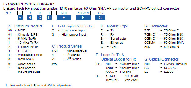
| Order Diagram - Options | ||
 |
||
Foxcom Platinum L-Band PL7220T [PL7220T1550] / PL7220R4 RF DownLink Low Input Power, 4dB Optical Budget
| RF Specifications | Units | Typical | Minimum |
Maximum |
| Frequency Range - Bandwidth | MHz | 950 - 3000 | 3000 | |
| Amplitude Response @ Unity Gain 950-3000 any 36 MHz |
dB |
±1.5 |
±2 |
|
| Gain Stability | dB/24hr | ± 0.2 | ± 0.25 | |
| Gain slope1 | dB | 0 | -1.5 | +1.5 |
| Gain Variation over temperature | dB | ± 1.5 | -2 | 2 |
| SFDR2 | dB/Hz2/3 | 99 | ||
| SFDR3 | dB/Hz2/3 | 91 | ||
| DR (Dynamic Range - single channel)4 | dB | 30 | ||
| CNR [any 36 MHz]2 | dB | 53 | 50 | 57 |
| Noise Figure (NF)2 | dB | 20 | 23 | |
| Noise Figure (NF)3 | dB | 8 | 11 | |
| Output IP3 (OIP3)4 | dBm | -5 | ||
| Group Delay Variation - linear 950 -1200 MHz 1200 - 3000 MHz |
ns | 3 1.5 |
||
| Input/Output Impedance | Ohm | 50 or 75 | ||
| 1 dB Compression Point [input] | dBm | -16 | -15 | |
| Phase noise6 | dB | None | ||
| Third Order InterModulation [IMD]4 | dBc | -55 | -40 | |
| Input Signal Range - Total Power7 | dBm | -55 | -25 | |
| Maximum input without damage | dBm | +15 | ||
| RF output Signal Range - Total Power -35 dBm input8 -55 dBm input9 |
dBm | -30 -35 |
-25 -25 |
|
| TX/RX Input/Output return loss 50 Ohm 75 Ohm10 |
dB | -15 -13 |
-15 -11 |
|
| Test port [front panel sample port]11 | dB | -20 | -22 | -18 |
| RF Connector Type Input/Output Test port |
F, SMA, N |
|||
| Optical Specifications | Typical | Minimum | Maximum | |
| Optical Wavelength | nm | 1310/1550/CWDM | ||
| Optical Power Output | mW/dBm | 2 / 3 | 1.7/2.5 | |
| Optical Budget / Distance 1310nm 1550nm |
dBm/km | 4dB / 8Km 4dB / 15Km |
||
| RX Optical Input Power | dBm | -1 | -2 | 4 |
| Optical Connector Types | Type | FC/APC or SC/APC (E2000 option) |
- | |
| Optical Return Loss | dB | -60 | -55 | |
| Electrical Specifications | ||||
| Supply Voltage | VDC | 12 | ||
| Supply Current [TX, no LNB]12 | Amps | 0.45 | ||
| Supply Current [TX with LNB]12 | Amps | 0.75 | 0.9 | |
| Supply Current (RX) | Amps | 0.45 | ||
| EMI Rating | EMI Rating: FCC part 15 Class A, CE Mark |
|||
| Physical Specifications | ||||
| Operating Temperature Range | ºC | -10 | +55 | |
| Storage Temperature Range | ºC | -45 | +85 | |
| Relative Humidity | 95% non-condensing | |||
| Altitude | ft / km | 10,000 [3.08 ] operating13 |
||
| Dimensions [D×W×H] | ins/cm | 12×0.8×4 / 30.5×2×10.2 | ||
| Weight | lbs./Kg | 0.5 / 0.23 | ||
| MTBF | hours | TX 309, 481 RX 359, 057 |
||
| MTTR | hours | 0.083 | ||
| Shock & vibration | Designed for normal transportation environment per section 514.4 MIL-STD-810E. Designed to withstand 20G at 11 ms [½ sine pulse] in non-operating configuration | |||
| 1. Within the flatness spec 2. -25 dBm RF input link gain =0 IMD=-40 dBc @ 3 dB opt. budget [0 dBm optical input - max .RF input] 3 -55 dBm RF input link gain = 30 IMD=-50 dBc @ 3 dB opt. budget [0 dBm optical input - min.RF input] 4. User adjustable 5.. -25 dBm RF input, IMD=-40 dBc 6. Direct modulation utilized 7. Alarm trip point: RED -22 dBm, AMBER -58 dBm 8. @ 0 dB optical loss 9. @ 4 dB optical loss 10. -15 dB @ 950 to 3000 MHz, -11 dB @ 2500 to 3000 MHz 11. -45 dBm minimum ooutput 12. under 10ºC add 120 mA [laser heating] 13. WIth standard adiabatic derating at 2ºC/1000ft. [0.3 Km.] |
||||