Foxcom Gold GL7130 RF Optical Link 10MHz Reference Signal, 4dB Optical Budget

Foxcom Gold GL7130 RF Optical Link 10MHz Reference Signal, 4dB Optical Budget
 |
||
| Summary | ||
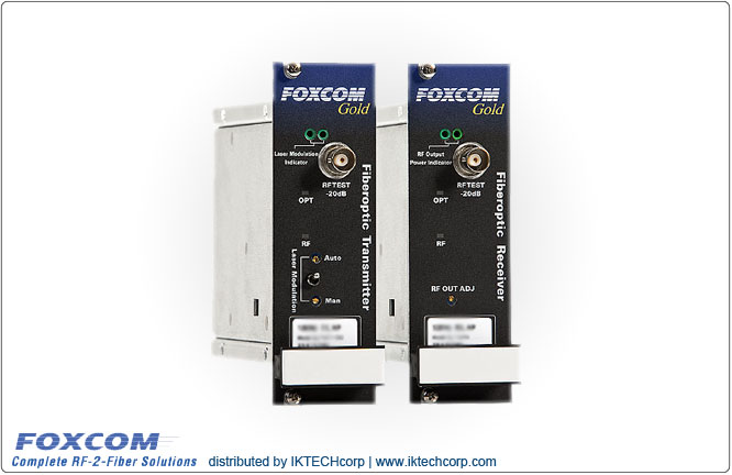
| Foxcom Gold GL7130 RF Optical Link 10MHz Reference Signal, 4dB Optical Budget Foxcom's Sat-Light/Gold 10MHz Reference Signal Link offers a high performance, cost effective alternative to conventional coaxial-cabled systems. The Gold 10MHz Reference Signal optical link is designed for to meet the needs of a wide range of Satellite and professional VSAT applications. Foxcom’s high dynamic range DFB laser delivers exceptional signal quality for the most demanding applications. The new Gold series is compatible with first generation Sat-Light 7000 Series platform. The Gold Series support L-Band, 70/140MHz IF, Wide Band (10-2200 MHz), 10MHz Reference, Redundancy, M & C, SNMP, Ethernet, and Serial Data Communication. The link consists of a high dynamic range optical transmitter, which converts incoming 10 MHz reference signals into optics, and an optical receiver that re-converts the optical signal back into RF. Inherently low phase is achieved by direct modulation of the laser diode. | ||
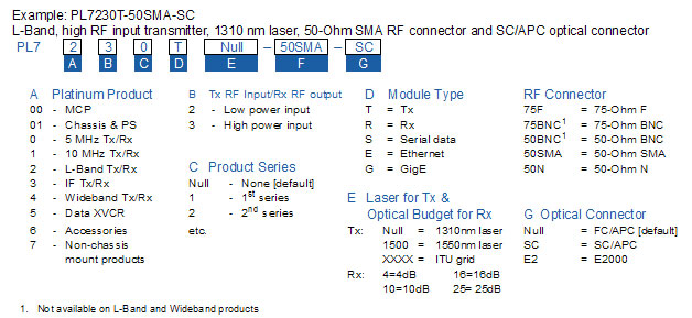
| Order Diagram - Options | ||
 |
||
Foxcom Gold GL7130 RF Optical Link 10MHz Reference Signal, 4dB Optical Budget
| RF Specifications | Units | Typical | Minimum | Maximum |
| Frequency Range | MHz | 10MHz | ||
| Link Gain | dB | Adjustable | -10 | +10 |
| Amplitude Response @ Unity Gain 5-15MHz |
dB | ±2.5dB |
||
| Gain Stability | dB/24hr | ±0.25 | ±0.3 | |
| SFDR1 | dB/Hz2/3 | 100 | ||
| CNR1 | dB | 65 | 60 | |
| Noise Figure (NF)2 | dB | 20 | 23 | |
| Output IP3 (OIP3) 3 | dBm | +30 | +20 | |
| Third Order InterModulation [IMD]4 | dBc | 55 | 40 | |
| Group Delay Variation - linear 10-20MHz | ns | 5 | 6 | |
| Input Signal Range - Total Power | dBm | -25 | +5 | |
| Output Signal Range - Total Power | dBm | -15 | +10 | |
| Maximum Input without Damage | dBm | +15dBm | ||
| Input/Output Impedance | 75 or 50 | |||
| TX/RX Input/Output return loss 50 Ohm 75 Ohm |
dB | -15 -13 |
-15 -13 |
|
| RF Connector Type Input/Output Test Port |
F, SMA BNC |
|||
| Test Port [front panel sample port] | dB | -20 | -22 | -18 |
| Optical Specifications | Unit | Typical | Minimum | Maximum |
| Optical Power Output | dBm | 3 | 2 | 4 |
| Optical Budget / Distance 4 dB optical budget |
dB/Km | 1310 nm | 1550 nm 8 |15 |
||
| Optical Connector Types | FC/APC or SC/APC | |||
| Optical Wavelength | nm | 1310/1550/CWDM | ||
| Electrical Specification | ||||
| Supply Voltage | Vdc | 13 | 12.7 | 18 |
| Supply Current [TX]5 | Amps | 0.4 | ||
| Supply Current (RX) | Ampls | 0.3 | ||
| Physical Specifications | ||||
| Operating Temperature Range | -10 | +55 | ||
| Dimensions [D×W×H] | ||||
| MTBF | Hours | TX: 309, 481 RX: 359, 057 |
||
1. -5 dBm RF input, link gain =10dB, IMD=-40 dBc @ 3 dB opt. budget |
||||