Bienvenido a IK Tech Corporation
Su única parada para todas sus necesidades de satélites

AvL 1030-T 1,0 m Militar Motorizado Tri-Banda FlyAway Trípode de la Antena de la banda Ka

AvL 1030-T 1,0 m Militar Motorizado Tri-Banda FlyAway Trípode de la Antena de la banda Ka

AvL 1030-T Antena trípode FlyAway de triple banda motorizada militar de 1,0 m 2 puertos Ka-Band

IKtechcorp es el distribuidor de AVL Antanna Systems, un fabricante y proveedor líder de equipos satelitales comerciales. AVL Technologies ofrece una amplia gama de antenas utilizadas en las industrias VSAT, DTH, COTM, Teleport, Cable y Broadcast. Satélite, DTH, VSAT, Flyaway, despliegue rápido, solo recepción, RF, punto automático motorizado, antenas de vehículos
• Rx/Tx Feed: 2 puertos Ka-Band Military
- Recibir:
- Transmitir:
<

Código: avl_1030-t_ka_mil

AvL 1030-T 1.0m Military Motorized Tri-Band FlyAway Tripod Antenna 2-port Ka-Band

AvL 1030-T 1.0m SNG/Military Motorized Tri-Band FlyAway Tripod Antenna 2-port Precision Ka-band Product Picture, Price, Image, Pricing
 
Summary

AvL 1030-T 1.0m Military Motorized Tri-Band FlyAway Tripod Antenna 2-port Ka-Band

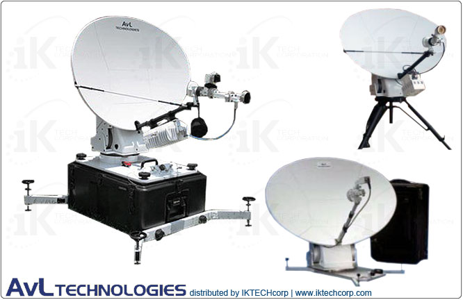
AvL's 1030-T positioner FlyAway Military antenna systems offer superior performance in a truly compact, lightweight and portable package. The 1.0m antenna systems are commercial airline checkable (two cases, each weighs <70 lbs) and can be flown or shipped anywhere, then set up and operational within minutes.   
 
AvL’s FlyAway Military antennas are designed to meet and exceed the highest performance requirements around the world to guarantee both satellite authority compliance and peak in performance, reliability and availability.

Each Flyaway Antenna is priced to include the AvL carbon fiber antenna and auto-acquisition controller for ease of operation. As with all AvL antenna systems, no laptop is necessary to operate the controller, the antennas interface with any modem, RF electronics, or satellite service

AvL 1030-T 1.0m Military Systems feature:
• Commercial airline checkable - packs into two cases, each weighs <70 lbs.
• Enhanced wind tolerance of 45 mph gusting to 60 mph for Ku operation
• 1.0m segmented 6-piece AvL carbon fiber reflector with optional (1.2m) extender panels
• Rugged AvL Cable Drive Case-Based Positioner
• Case-Based Positioner (AvL or CFE) or Rugged Tripod Mount
• Offset Prime Focus Highly Efficient Optics
• Available in Ku (precision or mode-match), X and Ka-band for commercial or military applications
• Motorized AvL Cable Drive for reliable positioning
• One button auto-acquisition controller
• Interfaces with all types of RF electronics and satellite services 
• MIL-STD-188-164A Compliant
• 15-Minute Setup

While the vast majority of military applications to date have relied on commercial satellite interoperability, especially at Ku-band, AvL is now leading the industry in the delivery of systems that will operate over the next generation of military satellites, including Xtar (X-band) and the new US Army Wideband Global Satellite (WGS) constellation (X- and Ka-band). Most of our military antennas can be offered with upgradability to X- and Ka-bands of operation.

AvL antennas interface easily with all RF systems and are compliant with FCC and Intelsat requirements for 2° spacing as well as optional models for meeting Eutelsat and Asiasat criteria. AvL antennas are also in the certification process for operation over the US Army DSCS and WGS satellites.


Technical Specifications Diagram    
Inquire

AvL 1030-T 1.0m Military Motorized Tri-Band FlyAway Tripod Antenna 2-port Ka-Band

MECHANICAL SPECIFICATIONS


Az/El Drive

Motorized AvL Zero Backlash Cable Drive (Patent Pending)

Polarization Drive System

Motorized/Manual Options depending on feed

Reflector Construction

1.0m Segmented 6-Piece AvL Carbon Fiber Reflector
(optional 1.2m segmented 10-piece reflector)


Axis Travel


Azimuth

±90°

Elevation (reflector boresight)

0° - 100° (7° - 100° over tripod legs)

Polarization ±95°
   

Az/El Speed:


Slewing/Deploying (typical) Azimuth: 2°/sec Elevation: 1°/sec
Peaking (typical) Azimuth: 0.2°/sec Elevation: 0.2°/sec
   

Motors

24 VDC Variable Speed, Constant Torque

   
Standard Interfaces:
BUC (& other CFE) Mounting Feed boom or behind reflector (additional CFE case or optional case required)
RF Std. 50 ohm Coax (2) at base, cover flange at feed Tx port
Electrical 30 ft. cable with connectors for controller


Electrical Interface

Connectors on base

   
Transit Configuration (Ku-band): Tripod-Based
Case 1: Positioner & Feed 31.3” x 20.4” x 15.5” (< 70 lbs)
Case 2: Reflector, Boom, Controls 31.3” x 20.4” x 15.5” (< 70 lbs)
 

ENVIRONMENTAL SPECIFICATIONS


Wind – Survival

80 mph in zenith position

Wind - Operational: ▼


Without Anchoring 30 mph
With Anchoring 30 mph gusting to 45 mph
   

Pointing Loss in Wind:


Ku-band

0.7 dB max (1.0m reflector)

Ka-band

2.0 dB max (1.0m reflector)

X-band 1.5 dB max (1.2m reflector with extender panels)
   

Temperature:


Operational

-22° to 125° F (-30° to 52° C)

Survival

-40° to 140° F (-40° to 60° C)


RF / ELECTRICAL SPECIFICATIONS

Receive Transmit
     

Feed Type

Opt. 2-Port Ka (Military/WGS)


Frequency Range (GHz)

20.2 - 21.2

30.0 - 31.0

Polarization Configuration

Circular or Linear

Gain (mid-band) @ Horn Interface (dBi)

44.6 dBi

47.9 dBi

-3dB Beamwidth (mid-band)

1.0°

0.7°

First Sidelobe Level (typical) -22 dB -25 dB

Antenna Noise Temperature (midband)

107° K @ 20.2 GHz


Radiation Pattern Compliance

Per MIL-STD-188-164A

Maximum Feed Transmit (Tx) Power   250W

VSWR

1.30:1

1.30:1

G/T with 50˚ LNB, midband, clear horizon 21.1 dB/K with 100ºK LNB  
Axial Ratio (CP only, within pointing cone ) 1.5 dB 1.0 dB

Port-to-Port Isolation – Tx to Rx

85 dB

85 dB (with filter)
 

CONTROLLER SPECIFICATIONS: STANDARD

   
Controller Type Std. Auto-Acquire with Opt. Ethernet IP Interface
Standard Feature  

Fully-automatic satellite acquisition, with automatic azimuth, elevation and cross-polarization peaking; includes on-board, one-button deploy/acquire interface for pre-configured systems; includes on-board GPS, electronic compass, level sensors and auto-compensation; customer-configurable satellite list. Note: Beacon Receiver or Modem as acquisition signal source may be required for non-commercial satellites

   
Integration Embedded w/ Handheld, incl. Shelf-Mount P/S (optional 1RU w/ front-panel keypad + integral P/S)
User Interface Menu-driven display w/ keypad
Input Power 115/230 VAC (at rack); up to 200W

Software Upgrades/Options

Inclined orbit tracking (using step-track or TLE track); automatic band sensing


CONTROLLER SPECIFICATIONS: OPTIONAL

   
Controller Type Opt. Enhanced Auto-Acquire with Ethernet IP Interface
Standard Feature  

Fully-automatic satellite acquisition, with automatic azimuth, elevation and cross-polarization peaking; includes on-board, one-button deploy/acquire interface for pre-configured systems; includes on-board GPS, electronic compass, level sensors and auto-compensation; customer-configurable satellite list. Note: Beacon Receiver or Modem as acquisition signal source may be required for non-commercial satellites

   
Integration Embedded w/ Ethernet IP Interface (P/S optional) (optional rack-mount P/S available)
User Interface Intelligent/simple GUI for on-board or remote CFE laptop
Input Power 28V DC (at antenna positioner); optional 115/230 VAC rack-mount power supply; up to 200W

Software Upgrades/Options

Inclined orbit tracking (using step-track, memory track, or TLE track); automatic band sensing


Available Options, Upgrades & Services


Optional:
• Upgrade from 2-Port Precision Ku Feed to:
a) 2-Port Enhanced Cross-Pol (Mode-Matched) Ku;
b) 2-Port X MIL;
c) 2-Port Ka
• BUC/HPA mounting
• Optional 75 ohm coax
• Waveguide interconnect options
• Beacon receiver – inclined orbit tracking – resolvers/upgrade
• Grounding options (lightning conductor)
• Anchoring kit options
• Custom logo on reflector face (1- or 2-color; per AvL Logo Policy)
• Spare parts kit
• Custom pack-ups


Technical Specifications Diagram

Inquire