AGILIS AUC28 Serie SI-Band/ Banda L Convertidor


Convertidor de banda L/IF-Band de la serie AGILIS AUC28
![]()
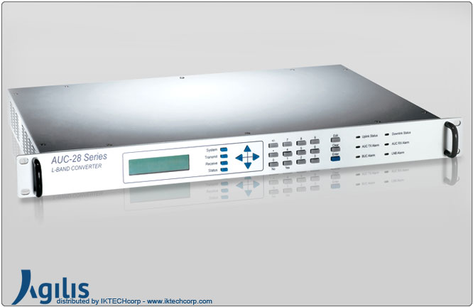
El AUC28 es una nueva serie rentable de banda ancha de 70MHz a convertidores de banda L. Tanto la cadena de transmisión como la de recepción tienen sintetizadores independientes. Estos convertidores se pueden configurar mediante un árbol de menú intuitivo desde un panel frontal LCD. También están equipados con puertos auxiliares de banda L opcionales en las cadenas de transmisión y recepción para el trabajo integrado con otros sistemas de banda L.
Los convertidores también se pueden configurar y monitorear de forma remota en una PC usando un RS232/Interfaz RS422 Proporcionan 24VDC, una referencia de ruido de fase muy estable y baja de 10MHz para el BUC y una de 15VDC y la referencia para LNB. El BUC y el LNB pueden manejarse con cables de hasta 200 pies.
Estos convertidores vienen en un rack estándar de 19 ”de 1RU de altura.
AGILIS AUC28 Series IF-Band/ L-Band Converter
 |
| Summary |
| The AUC28 is a new, wideband cost effective series of 70MHz to L-Band Converters. Both the transmit and receive chains have independent synthesizers. These converters can be configured using an intuitive menu tree from a LCD front panel. They are also equipped with optional L-Band auxiliary ports both on the transmit and receive chains for integrated working with other L-Band systems. The Converters can also be configured and monitored remotely on a PC using an RS232/RS422 interface. They provide 24VDC, a very stable and low phase noise reference of 10MHz for the BUC and a 15VDC and the reference for LNB. The BUC and LNB can be driven with cables up to 200ft. These converters come in a standard 19” Rack of 1 RU height. |
| Features |
| • Extremely cost competitive • Independent TX/RX synthesizers • Highly reliable • Front panel control • Remote control using PC • Low spurious emission meeting EN standards • Built-in Redundancy control unit • Very high dynamic range both for transmit and receive chains • Extremely stable reference oscillator • Wide transmit frequency range from 950 to 1750MHz • Wide receive frequency range from 950 to 1750MHz • Operates over 0ºC to +50ºC |
| Reliability |
| All Agilis IDUs are designed and manufactured according to ISO 9001 Standard. |
AGILIS AUC28 Series IF-Band / L-Band Converter Specifications
|
||||||||||||||||||||||||||||||||||||||||||||||||||||||||||||||||
|
||||||||||||||||||||||||||||||||||||||||||||||||||||||||||||||||
|
||||||||||||||||||||||||||||||||||||||||||||||||||||||||||||||||
|
||||||||||||||||||||||||||||||||||||||||||||||||||||||||||||||||
|
||||||||||||||||||||||||||||||||||||||||||||||||||||||||||||||||
|
||||||||||||||||||||||||||||||||||||||||||||||||||||||||||||||||
|
||||||||||||||||||||||||||||||||||||||||||||||||||||||||||||||||
|
||||||||||||||||||||||||||||||||||||||||||||||||||||||||||||||||
|
||||||||||||||||||||||||||||||||||||||||||||||||||||||||||||||||