AGILIS AUC28 Série SI-Bande/ Bande L Convertisseur


Convertisseur AGILIS AUC28 Series IF-Band/L-Band
![]()
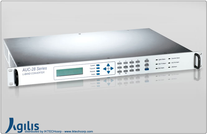
L'AUC28 est une nouvelle série rentable de convertisseurs 70 MHz vers bande L à large bande. Les chaînes d'émission et de réception ont des synthétiseurs indépendants. Ces convertisseurs peuvent être configurés à l'aide d'une arborescence de menus intuitive à partir d'un panneau avant LCD. Ils sont également équipés de ports auxiliaires en bande L en option sur les chaînes de transmission et de réception pour un fonctionnement intégré avec d'autres systèmes en bande L.
Les convertisseurs peuvent également être configurés et surveillés à distance sur un PC à l'aide d'un RS232/Interface RS422. Ils fournissent 24VDC, une référence très stable et à faible bruit de phase de 10MHz pour le BUC et un 15VDC et la référence pour le LNB. Le BUC et le LNB peuvent être pilotés avec des câbles jusqu'à 200 pieds.
Ces convertisseurs sont livrés dans un rack standard de 19" d'une hauteur de 1RU.
AGILIS AUC28 Series IF-Band/ L-Band Converter
 |
| Summary |
| The AUC28 is a new, wideband cost effective series of 70MHz to L-Band Converters. Both the transmit and receive chains have independent synthesizers. These converters can be configured using an intuitive menu tree from a LCD front panel. They are also equipped with optional L-Band auxiliary ports both on the transmit and receive chains for integrated working with other L-Band systems. The Converters can also be configured and monitored remotely on a PC using an RS232/RS422 interface. They provide 24VDC, a very stable and low phase noise reference of 10MHz for the BUC and a 15VDC and the reference for LNB. The BUC and LNB can be driven with cables up to 200ft. These converters come in a standard 19” Rack of 1 RU height. |
| Features |
| • Extremely cost competitive • Independent TX/RX synthesizers • Highly reliable • Front panel control • Remote control using PC • Low spurious emission meeting EN standards • Built-in Redundancy control unit • Very high dynamic range both for transmit and receive chains • Extremely stable reference oscillator • Wide transmit frequency range from 950 to 1750MHz • Wide receive frequency range from 950 to 1750MHz • Operates over 0ºC to +50ºC |
| Reliability |
| All Agilis IDUs are designed and manufactured according to ISO 9001 Standard. |
AGILIS AUC28 Series IF-Band / L-Band Converter Specifications
|
||||||||||||||||||||||||||||||||||||||||||||||||||||||||||||||||
|
||||||||||||||||||||||||||||||||||||||||||||||||||||||||||||||||
|
||||||||||||||||||||||||||||||||||||||||||||||||||||||||||||||||
|
||||||||||||||||||||||||||||||||||||||||||||||||||||||||||||||||
|
||||||||||||||||||||||||||||||||||||||||||||||||||||||||||||||||
|
||||||||||||||||||||||||||||||||||||||||||||||||||||||||||||||||
|
||||||||||||||||||||||||||||||||||||||||||||||||||||||||||||||||
|
||||||||||||||||||||||||||||||||||||||||||||||||||||||||||||||||
|
||||||||||||||||||||||||||||||||||||||||||||||||||||||||||||||||