AvL 1220FA 1,6 m Militaire Motorisé Tri-Bande envolez-vous de l'Antenne en Bande X

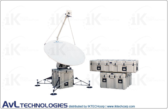
AvL 1220FA 1.6m Military Motorized Tri-Band FlyAway Antenna 2-port Precision X-Band
![]()
• Rx/Tx Feed: 2-port X-band (Military/WGS)
- Receive: 7.25 - 7.75 GHz
- Transmit: 7.9 - 8.4 GHz
• Packs into three rugged cases
• 1220 Case-Based Positioner
• Key Features
- 15 minute set-up
- Zero Backlash AvL Cable Drive
- Auto-Acquisition Controller
AvL 1220FA 1.6m Military Motorized Tri-Band FlyAway Antenna 2-port Precision X-Band
 |
||
| Summary | ||
| AvL 1220FA 1.6m Military Motorized Tri-Band FlyAway Antenna 2-port Precision X-Band
AvL's Model 1.6m 1220 FlyAway Military antenna systems offer enhanced wind performance in a lightweight, portable, 2-man lift package. All 1220FA FlyAway Military antenna systems have positioners integrated into cases for easy set-up; these antennas can be flown anywhere, then set up and operational within minutes. AvL’s FlyAway Military antennas are designed to meet and exceed the highest performance requirements around the world to guarantee both satellite authority compliance and peak in performance, reliability and availability. Each Flyaway Antenna is priced to include the AvL carbon fiber antenna and auto-acquisition controller for ease of operation. As with all AvL antenna systems, no laptop is necessary to operate the controller, the antennas interface with any modem, RF electronics, or satellite service. AvL 1220FA X-Band 1.6m Military Systems feature: • Packs into two rugged cases • Enhanced wind tolerance of 45 mph gusting to 60 mph for Ku operation • 1.6m Segmented 4-piece Carbon Fiber Reflector • Easy 2-man lift - weighs <150 lbs • 1220 case-based positioner • Tri-band feed capability: -Ku-Band (LP) -Ka-Band (LP or CP) -X-Band (CP) -C-Band (LP or CP) available for some international locations • Az/El drive system with patented AvL Cable Drive Positioner • Elevation over azimuth mount geometry • Polarization adjustment by motorized rotation of linear feeds • Case-based systems with the positioner integrated into one case for stability and ease of set-up • Fully compliant for FCC, Intelsat and WGS • One button auto-acquisition controller • 15-Minute Setup While the vast majority of military applications to date have relied on commercial satellite interoperability, especially at Ku-band, AvL is now leading the industry in the delivery of systems that will operate over the next generation of military satellites, including Xtar (X-band) and the new US Army Wideband Global Satellite (WGS) constellation (X- and Ka-band). Most of our military antennas can be offered with upgradability to X- and Ka-bands of operation. AvL antennas interface easily with all RF systems and are compliant with FCC and Intelsat requirements for 2° spacing as well as optional models for meeting Eutelsat and Asiasat criteria. AvL antennas are also in the certification process for operation over the US Army DSCS and WGS satellites. |
||
| Technical Specifications Diagram | ||
| Inquire | ||
AvL 1220FA 1.6m Military Motorized Tri-Band FlyAway Antenna 2-port Precision X-Band
|
||||||||||||||||||||||||||||||||||||||||||||||||||||||||||||||||||
|
||||||||||||||||||||||||||||||||||||||||||||||||||||||||||||||||||
|
||||||||||||||||||||||||||||||||||||||||||||||||||||||||||||||||||
|
||||||||||||||||||||||||||||||||||||||||||||||||||||||||||||||||||
|
||||||||||||||||||||||||||||||||||||||||||||||||||||||||||||||||||
|
||||||||||||||||||||||||||||||||||||||||||||||||||||||||||||||||||
|
||||||||||||||||||||||||||||||||||||||||||||||||||||||||||||||||||