| MECHANICAL SPECIFICATIONS |
| |
|
| Az/El Drive |
Motorized AvL Zero Backlash Cable Drive (Patent Pending) |
| Polarization Drive System |
Motorized Worm Gear Drive |
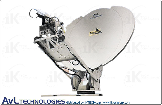
| Reflector Construction |
1.2m Single Piece Carbon Fiber |
| Axis Travel ▼ |
|
| Azimuth |
400° (±200°) |
| Elevation ▼ |
|
| Mechanical |
0° to 90° of Reflector Boresight |
| Electrical |
Standard Limits at 5° to 65° (CE approval) or 0° to 90° |
| Polarization |
±95° for 2-port and 3-port Feeds; ±50° for 2-port Wideband and 4-port Feeds |
| Az/El Speed ▼ |
|
| Slewing/Deploying (typical) |
2°/second Az; 1°/second El |
| Peaking (typical) |
0.2°/second |
| Motors |
24 VDC Variable Speed, Constant Torque |
| RF Interface ▼ |
|
| BUC/HPA Mounting |
Feed Boom (50 lbs.; Max. BUC envelope: 22 L x 13.75 W x 8.5 H inches (55.9 L x 34.9 W x 21.6 H cm)), Rear of Reflector or Inside Vehicle |
| Axis Transition |
Twist-Flex or Rotary Joints |
| Waveguide |
WR75 Cover Flange at Interface Point |
| Coax |
RG59 run from feed to base plus 25 ft (8m) |
| Electrical Interface |
One 25 ft (8 m) Cable with Connectors for Controller |
| Manual/Emergency Drive |
Handcrank on Az, El and Pol axes |
| Weight (approximate) |
115 - 165 lbs. (52 - 75 kg) depending on options selected |
| Stowed Dimensions |
69 L x 48 W x 16.3 H inches (175 L x 122 W x 41 H cm) |
|
| |
| ENVIRONMENTAL SPECIFICATIONS |
| |
|
| Wind - Survival |
Deployed: 75 mph (121 kph); Stowed: 100 mph (161 kph) |
| Wind - Operational |
30 mph (48 kph), Gusts to 45 mph (72 kph) |
| Pointing Loss in Wind (Ku RX): ▼ |
|
| 20 mph (32 kph) |
0.2 dB typical |
| 30 mph gusting to 45 mph |
0.8 dB typical |
|
|
| Temperature: ▼ |
|
| Operational |
-22° to 125° F (-30° to 52° C) |
| Survival |
-40° to 140° F (-40° to 60° C) |
|
| |
| RF / ELECTRICAL SPECIFICATIONS |
Receive |
Transmit |
| |
|
|
| Feed Type |
Std. 2-Port Ku-Band DBS bands avail. upon request |
|
|
|
| Frequency Range (GHz) |
10.95 - 12.75 |
13.75 - 14.50 |
| Polarization Configuration |
Linear Orthogonal Standard, Optional Co-Pol |
| Gain (mid-band) (dBi) |
41.6 |
43.1 |
| Beamwidth (-3 dB) |
1.5° |
1.2° |
| G/T, midband, clear horizon |
21.4 dB/˚ K with 50° LNB |
|
| Antenna Noise Temperature @ 20° El, midband |
54° K |
|
| Radiation Pattern Compliance |
FCC 25.209, ITU-R S.580-6, IESS 208 |
| Power Handling Capability |
|
1 KW per port |
| VSWR |
1.30:1 |
1.30:1 |
| Axial Ratio, CP only, within Pointing Cone (dB) |
|
|
| Cross-Polarization Isolation (dB) ▼ |
|
|
| On Axis |
35 |
35 |
| Within Pointing Cone |
28 Std. Precision |
30 Std. Precision |
|
25 Mode-Match |
35 Mode-Match |
| Feed Port Isolation – Tx to Rx (dB) |
35 |
80 (includes filter) |
|
| |
| CONTROLLER SPECIFICATIONS |
| |
|
| Controller Type ► |
Three-axis Jog Control & Display with Auto-Stow |
| Optional Upgrades |
|
| Semi-automatic Operation |
Drive to calculated position based on operator entered vehicle location, heading, plus satellite (longitude or listed) |
| Automatic Operation |
Drive to calculated position based on auto GPS and Flux-Gate Compass data and satellite peaking with LNB signal |
| Auto-acquisition |
One-button acquisition of selected satellite including peaking and optimization of cross-pol (certified for auto- commissioning on most satellite services) |
| Size |
Two Rack Units for Semi-automatic & Automatic Controllers Single Rack Unit for Auto-acquisition |
| Input Power |
110/240 VAC, 1 ph, 50/60 Hz, 6/3A peak, 1A continuous |
|
| |
| CONTROLLER SPECIFICATIONS: OPTIONAL |
| |
|
| Optional Controller ► |
AvL AAQ |
| Features |
AvL one button auto-acquisition of selected satellites, including peaking and optimization of cross pol. Internal movement detector and automatic stow. Includes a hand-held control and separate power supply. Certified for auto-commissioning on most satellite services. |
| Size |
Embedded ACU with separate1 RU power supply |
| Input Power |
100 - 240 VAC 50/60 Hz 4 A peak, 300 W power supply |
|
| |
| Available Options, Upgrades & Services |
| |
• Upgrade Feed to:
- 2-Port Ku-Band Mode-Match
- 4-Port Ku-Band Wideband
- 2 or 4-Port Ka-Band
- 2-Port X-Band
• Optional H/V switch (Ku-Band wideband)
• Optional Rotary Joint on Pol Axis with opt. Flex W/G to BUC
• Add Co-polarization Kit (for 2-port Ku feeds only) - configures Rx and Tx to same polarization sense
• Mounting Pallet (adds 2.0” (5 cm) to stow height)
• Add BUC/HPA Mounting (NOTE: minimum elevation may be restricted by these options)
• Upgrade to Custom RF/IF I/O cabling configurations available
• Custom Colorization (contact factory for available colors)
• Add Custom Logo on Reflector Face (1- or 2-Color; per AvL Logo Policy)
• Spare Parts Kit |
|
| |
| Technical Specifications Diagram |
| Inquire |
|
| |
| Compliance Standard |
| Inquire |
|